
A STEP-BY-STEP PROCEDURE TO BUILD A SIMPLE AUDIO AMPLIFIER.
An amplifier is a device that increases the strength (amplitude) of a signal or sound.
It takes a weak input signal and produces a stronger output signal, usually with the same waveform but a larger amplitude.
Amplifiers are essential in various electronic devices, such as:
- audio systems,
- radios,
- televisions,
- and telecommunications equipment
It boosts signals for better transmission.
Materials needed:
- LM386,
- 10 μF electrolytic capacitor (2 pieces),
- 047 μF ceramic capacitor (1 piece),
- 10 Ohm resistor (1 piece),
- 1k Ohm resistor (1 piece),
- potentiometer (10k Ohm, for volume control),
- speaker (8 Ohms, small size),
- audio input jack (3.5mm stereo jack),
- battery (9V battery with battery clip),
- breadboard or PCB (Printed Circuit Board),
- connecting wires,
- soldering kit (if using PCB)
You May Also Read:
-
How to Build an LED Circuit and a Light-Dependent Resistor Circuit.
-
Solar Panels and Application of Solar Energy in Practical Daily Activities.
-
AIR MASSES AND THEIR MOVEMENTS
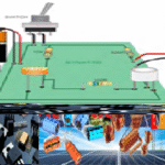
Step-by-Step Procedure:
- Place the LM386 IC in the middle of the breadboard or PCB for easy wiring.
- Connect the 9V battery clip to the breadboard or PCB.
- Connect the positive terminal of the battery clip to pin 6 of the LM386.
- Connect the negative terminal of the battery clip to the ground rail on the breadboard or PCB.
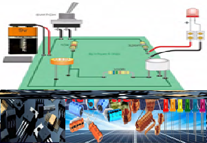
- Connect the audio input jack’s ground (sleeve) to the ground rail on the breadboard.
- Connect the audio input jack’s left or right channel (tip or ring) to one terminal of the 10k Ohm potentiometer.
- Connect the wiper (middle terminal) of the potentiometer to pin 3 of the LM386.
- Connect a 10 μF electrolytic capacitor between pin 7 and the ground.
- Ensure the negative leg of the capacitor goes to the ground.
- Connect a 10 μF electrolytic capacitor between pin 1 and pin 8 of the LM386 to set the gain to 200. Ensure the negative leg is on pin 1.
- Connect a 0.047 μF capacitor between pin 5 of the LM386 and one terminal of the 10-Ohm resistor.
- Connect the other terminal of the 10 Ohm resistor to the speaker’s positive terminal.
- Connect the negative terminal of the speaker to the ground rail on the breadboard or PCB.
- Connect a 220 μF capacitor’s positive leg to pin 5 of the LM386 and its negative leg to the junction between the 0.047 μF capacitor and the 10 Ohm resistor.
- Double-check all connections to ensure they are correct.
- Attach the 9V battery to the battery clip.
- Plug an audio source into the input jack and adjust the potentiometer to control the volume.
- You should hear the amplified audio through the speaker.
NOTE:
Capacitor
- It stores energy in the form of an electrical charge and releases the energy when needed.
- They are commonly used for smoothing voltage fluctuations and filtering out noise in power supplies.
Resistor
- This device restricts the flow of electric current in a circuit, helping to control voltage levels and protect sensitive parts
Diodes
- Diodes allow electric current to flow in only one direction and are often used to convert AC (alternating current) to DC (direct current) in power supplies.
Transistors
- These amplify or switch electronic signals.
- They are crucial in amplifiers, computers, and various digital devices.
Inductors
- Inductors store energy in a magnetic field and are commonly used in filters, transformers, and power supplies.